STAY TUNED
Learn more about DevOpsCon
When designing distributed systems, a lot of time is often spent on working out the best possible division into components. You don’t want to be monolithic. This is usually clear from the outset. Not for principled reasons, of course, but because it quickly becomes apparent during requirements analysis that certain system parts must scale separately. Other parts want to be isolated for security reasons, and teams generally want to benefit from establishing a strict division of responsibility and authority, both in the software system and among developers. Now divisions are made – according to aspects of Domain-Driven Design, and on the basis of technical considerations. What data is allowed in the cloud; which service needs to know what; do we need relational data structures?
Often, communication comes up short
Unfortunately, not as much time is spent thinking about communication in the system. When it does, it’s often a fairly technical consideration: Service A needs access to certain data as directly as possible. Because it’s voluminous, too much latency enters the system otherwise. After some discussions, services A and C are split into two parts. They are supposed to work closely together and therefore, communication paths between them have to be physically short.
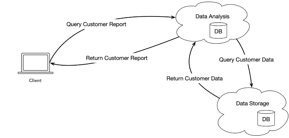
I’ve illustrated a simple service scenario in Figure 1. The client on the left is trying to retrieve some information about customers from a service called Data Analysis (Query Customer Report). In order to compute and provide this information, the Data Analysis service must first contact the Data Storage service and request basic data. Basically, it can generate and deliver the requested information.
Fig. 1: Simple service scenario with databases
In the diagram (Fig. 1), there has already been a step towards technical optimization, as previously described. Both services have been given a database to work alongside. In the example, we can assume that the Data Analysis service stores information in order to save as much time as possible for new queries for similar data.
Call chains grow fast
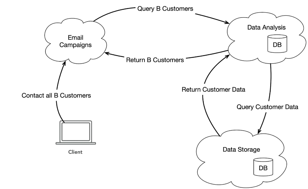
I added a step in Figure 2. The two previously mentioned services are still there, but now the Data Analysis service is not directly requested by the client, but by a new service called “Email Campaigns”. The scenario is that the client contacted this service to start an email campaign and send an email to all B clients. We’ll leave it at that and how a B-customer is defined in this context. However, to find out who the B-customers are, the Email Campaigns service uses information from the Data Analysis service. Therefore, the responsibilities in this sample system are divided quite logically.
Fig. 2: Extended scenario with service for email campaign
In the scope of this article, I don’t want to make these diagrams bigger and bigger. So let’s make a mental leap. The chain of calls that might be needed to complete a particular task gets longer as the system complexity increases. In fact, it would probably be much longer in most real-world systems even for these simple examples.
Programmers know this problem well, since it exists in areas besides distributed systems. There are chains of calls in every computer program. They are often long that problems arise, for instance, because several people are involved in programming and no one has an overall view and thinks carefully about what the process looks like as a whole each time a change is made. Therefore, it’s not uncommon for the call chain to be less than optimal. It can even be error-ridden and under certain circumstances, calls suddenly occur circularly. When classes and their instances come into play, persistence of certain object states, or event-driven logic as in database triggers or client UIs, this problem becomes more severe. We’ve all experienced it.
This can also happen in distributed application systems. This especially contributes to the fact that these systems are seen to be complicated. When multiple teams are working on different services, when services are hosted separately and differently, when there are many services in microservices and they are all running on different platforms, with different languages, the problem is severe. And since complex systems with unclear communication paths are usually a reflection of the companies that created them (see Conway’s Law [1]), joint discussion and problem solving in these cases is also difficult.
Proposed solution: CQRS and event sourcing
In the following, I’d like to present the patterns CQRS and Event Sourcing as a potential solution to this dilemma. There are many implementations based on them, which differ depending on requirements and on the platform or programming language. For example, different solutions are often worked out in dynamic languages instead of statically typed languages. My proposal is based on my own preferences, experience, and recommendations.
I’ll start at the beginning, with just CQRS. The concept isn’t new, and essentially, it consists of deliberately considering, setting up, or assessing the execution paths for commands and queries in a system separately. CQRS means “Command/Query Responsibility Segregation”, i.e. a strict separation of responsibilities of commands and queries.
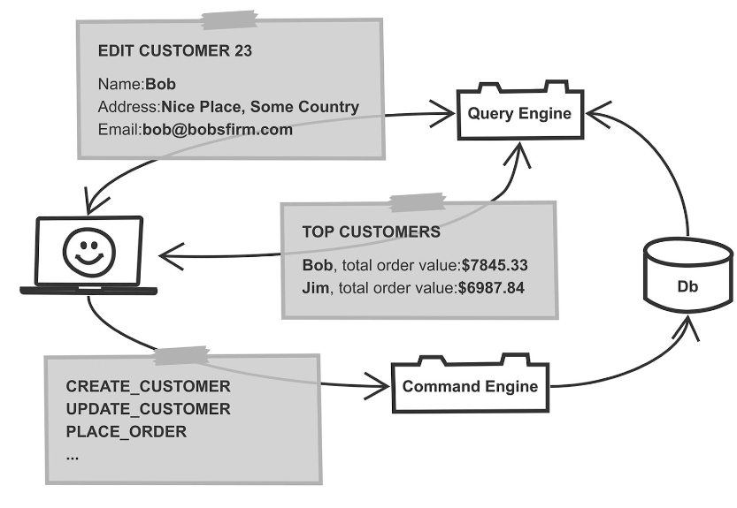
Now, we’ve heard all the technical terms regarding CQRS, but what does it mean? Figure 3 shows another diagram for this.
Fig. 3: Example for Command/Query Responsibility Segregation
In the lower part of Figure 3, you’ll see an architecture element called “Command Engine” that receives commands from the client. From the example naming of these commands, it’s clear what a command actually is. It is an active operation in the system, such as the creation of a new entity, or some other business logic operation. In the diagram, these commands cause something to be stored in the database (shown in the right margin).
Commands and queries each use several different data models
The specific design can vary. The important thing is that the commands are different from queries, as shown in the upper part of Figure 3. Queries return data from the system, for example, by a query engine. Of course, the logical way to query data is fundamentally different from the way to store data. However, the pattern CQRS recognizes the following essential points:
- The execution paths for queries and commands aren’t identical or even similar. Consideration should be given to implementing them differently with the most efficient means in each case. Thisdivision is also useful because the separate execution paths can then be optimized separately later. Separate scalability of both aspects is important.
- The data models for commands and queries also differ. For example, the diagram contains a CREATE_CUSTOMER command. When a customer is created, certain values are implied; in a typical query, not all of these values will be included later.
- In fact, for a query that refers in whole or in part to details of customers, there are usually several data models. In the example, a distinction is made between a query called TOP CUSTOMERS and one called EDIT CUSTOMER 23. The customer details that are queried to populate an edit form are not the same as those contained in a list of “best customers”.
- It’s the same with the commands. Here, besides CREATE_CUSTOMER, there is also UPDATE_CUSTOMER. Typically, when an entity is changed, not all of the values that were specified when it was first created can be changed.
In summary, CQRS recognizes that creating data by business logic functions should be considered technically separate from the subsequent querying of data. Furthermore, the pattern assumes that data should be managed in different structures on the command side and leave the system in different structures on the query side. This basic idea is similar to other patterns like MVVM. Again, we prepare data so that it is perfectly structured specifically for display in a view, and add mechanisms to invoke business logic that are optimized for the required bindings.
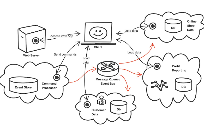
Pattern event sourcing can be considered independently of CQRS. But implementing a system in practice is difficult if we intend to disregard the fundamentals of CQRS. To illustrate this, let’s take a look at Figure 4.
Fig. 4: Example of the event sourcing pattern
Apart from the client, there are four services here: the “Command Processor”, “Customer Data”, “Online Shop Data”, and “Profit Reporting”. These services won’t likely be found exactly this way very often in an application system. The names are only here so you can better understand their potential responsibilities. Especially in microservices systems, systems are usually defined more granularly. If you follow DDD guidelines, you’re also likely to create other splits.

Kubernetes Training (German only)
Entdecke die Kubernetes Trainings für Einsteiger und Fortgeschrittene mit DevOps-Profi Erkan Yanar
The most important step: Commands become events, and we remember them
The Command Processor is the most important component in the event sourcing system. In a CQRS spirit, it accepts incoming commands.
It checks the commands for technical validity and maintains a set of aggregates for this. Typically, commands are addressed to aggregates, like with type and ID. Exactly how far the validity check should go is a philosophical question. Some developers would like to cover everything up to business logic, but that would require the Command Processor to act cross-domain in the sense of DDD. To others in development, that is a huge red flag. I prefer to keep the validation on a purely technical level to prevent the creation of two aggregates with the same ID.
After the validation has been passed, the Command Processor generates an event based on the received command. This event usually corresponds largely to the command, often containing some additional values like a timestamp. Some systems also create several events from one command, but this is another complexity I personally like to avoid. The event is now stored by the command processor in a database, or more precisely in a table: the event store.
The Event Store is the sequential list of all events that have ever occurred in the system, and therefore, it is the central source of all of the system’s information. The Event Store is immutable. The only kind of modification it supports is appending events to the end. Technically, you can use any database for this, but there are also special solutions like the helpfully named Event Store project [2].
In a sense, from this point, our duties are done. From the point of view of the event sourcing system, it’s now guaranteed that the system can accept and record the supported commands so that nothing is lost. But work with the system is still unsatisfactory from the user’s point of view.
The read side makes sure that users also see something
To give users something that can be displayed on the screen, we need the “read side” of CQRS. The three services already described – Customer Data, Online Shop Data, and Profit Reporting – represent this read side in the example. They are called read models.
After the Command Processor has created and stored the event, it sends it on to other interested parties in the system. The diagram in Figure 4 shows a component labeled “Message Queue / Event Bus” for this. It should be clear that the exact nature of this infrastructure component isn’t very important. Here, messages can be made available to everyone. There can also be a more formal publish/subscribe system or dedicated channels based on the type of events, for instance. In some event-driven architectures, there are also different streams used per DDD domain. These details can be designed according to the larger project requirements, but it’s also possible to do so without these additions.
At its core, the infrastructure should ensure that a Read Model interested in specific events can reliably receive those events as they occur in the system.
Basically, it’s now up to the Read Model what it does with the information from the events. The only important thing is that the Read Model should serve CQRS’ read side. If a client contacts a Read Model to execute a query, as shown in the diagram (Fig. 4) with the “Load Data” arrows, then the Read Model should be able to supply the necessary data. The expectation is generally that the Read Model already has the data in an efficient form for the query’s data model. At the time of the query, there shouldn’t be any need for computation and restructuring. All necessary computation and other time-consuming work should have been done when the data was read from the event stream. We call this process projection. Projection is the transfer of data from the event structures into a format later suitable for answering queries.
The concept is highly flexible. In the diagram shown in Figure 4, you’ll see the Customer Data service, which hypothetically holds all data about customers. These services do sometimes exist, although they don’t conform to the basic idea that data should be held in query-specific structures. For example, a service might make a model available that’s driven by the client with dynamic queries, like OData or GraphQL.
An example process flow in detail
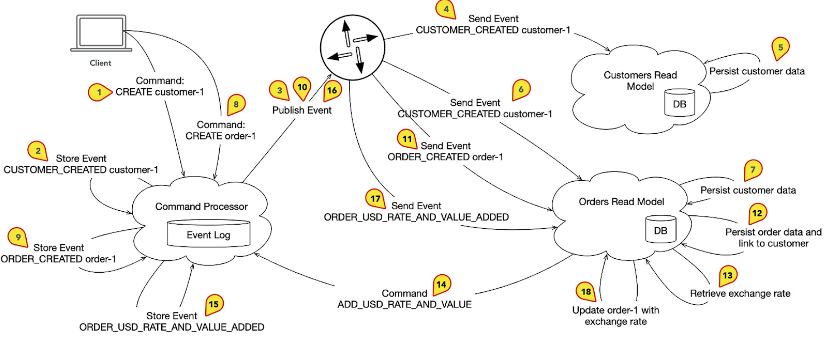
Figure 5 shows an example flow of business logical processes. The Read Models are for illustrative purposes only.
Fig. 5: Example flow of business logical processes in detail.
These are the steps briefly summarized:
- The client sends a CREATE command to create a customer (1).
- The Command Processor generates a CUSTOMER_CREATED event (2) and forwards it to the system (3).
- The event reaches the Read Model Customers (4) and is processed. The Read Model stores certain data about the customer in its own database (5).
- Meanwhile, in parallel, the event also reaches the Read Model Orders (6), and customer information that is later also relevant for order data is persisted (7).
- The client sends a command CREATE, which creates an order (8).
- The event ORDER_CREATED is generated (9), sent to the system, (10) and reaches the Read Model Orders (11).
- The Read Model persists data from the new event and establishes the relationship to the customer whose details were stored in step 7 (12).
From this point on, there are some additional elements in the diagram that we haven’t addressed yet. A side effect is triggered and the Read Model Orders starts an external query and looks up an exchange rate (13). When the information is available, the Read Model sends a command to the Command Processor (14). It’s then converted into an event (15), sent to the system (16), returns to the Read Model (17), and is incorporated into the Orders data (18). This part of the example illustrates a more complex relationship. Commands in an event sourcing system can be sent from sources other than just the client. The event store is always the central source of all information, sometimes called the single source of truth.
Autonomous data management leads to autonomous services
One important point: Read Models are autonomous. In the example, both the Read Model Orders and the Read Model Customers store information about the customer. Therefore, the databases of both Read Models potentially contain overlapping information. This is correct. In a complex system, these two databases could be different types, like a relational and document-based NoSQL database. They could have been built at different times by different teams on different platforms.
The elegance of this system is that all information can be derived from the Event Store. This happens continuously in normal operation, while the events run through the system, listening to the Read Models and projecting everything they need later. However, you can also regenerate all or part of a Read Model as needed. There is a huge amount of flexibility. As a developer, who hasn’t wished that a data error could be entirely erased simply by regenerating it in the background?
Another important point represents the core of this article. Communication channels in the described system are unidirectional. When the Read Model Orders needs information about the customer, it doesn’t go to the Read Model Customers to request it. It is the responsibility of each Read Model to read the data from the event stream that it needs immediately or later.
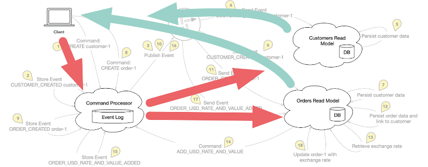
Fig. 6: Information flow between client, command processor, and read models
In this system, information flows from the client to the Command Processor. From there, it finds its way to the Read Models in the form of the events (red arrows in Fig. 6). Finally, the client queries the Read Models (green arrows in Fig. 6). These steps were not included in Figure 5, as they can occur at any time and are not part of the sequence of a particular logical flow.
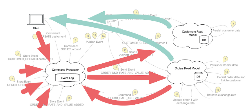
By including the side effect (steps 13 to 18 in the flow), this flow expands. Now, the Command Processor can receive commands from various sources (Fig. 7). This is generally the case because commands can be generated by other processes besides interactive clients, like import services or other automatic processes.
Fig. 7: The Command Processor receives commands from various sources
Therefore, the path from a Read Model to the Command Processor doesn’t represent a break in communication lines. By the way, some architects use a variant of the Read Model, called the Saga, for connecting side effects. Sagas are similar to Read Models, but have no or limited capabilities to be queried from the outside (e.g. only for status information or the like). In return, they support triggering side effects.
I don’t find the strict separation of Read Models and Sagas particularly important. However, it shows that the described return path for commands from the Read Models can be enclosed in a particular way.
Success: No more long call chains
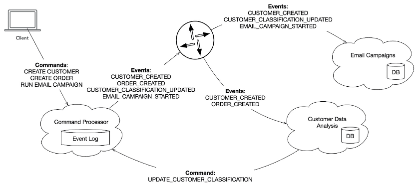
To close the circle, let me return to the email campaign example from earlier. Unlike the growing call chain when using services that call each other, the structure with event sourcing looks something like Figure 8.
Fig. 8: Structure of the call chain for event sourcing
The graphic shows the following steps:
- The CREATE CUSTOMER command generates a CUSTOMER_CREATED event and the Read Model (or Saga) Email Campaigns remembers relevant info about the customer. The Read Model Customer Data Analysis also remembers data about the customer, although not exactly the same as Email Campaigns.
- The CREATE ORDER command creates an ORDER_CREATED event. The Read Model Customer Data Analysis adjusts its customer ratings according to the new order information. The assessment of who is a B customer can be queried by the Read Model (for display in the UI, for example). The Read Model also sends an UPDATE_CUSTOMER_CLASSIFICATION command to the system when a particular customer’s rating changes.
- The UPDATE_CUSTOMER_CLASSIFICATION command results in the creation of a CUSTOMER_CLASSIFICATION_UPDATED event, which is received by the Email Campaigns Read Model. The Read Model remembers the ratings of customers, since it might need them in the future for targeted campaigns.
- The command RUN EMAIL CAMPAIGN creates an event EMAIL_CAMPAIGN_STARTED, which is received by the Read Model Email Campaigns. Info for selecting the right customers for the campaign is already available. The Read Model (or the Saga) triggers a side effect that leads to sending emails.
Ultimately consistent
One final issue that I want to briefly mention is implementing automatic change notifications between Read Models and clients. Distributed architectures like the ones in my examples are inherently “eventually consistent”. That is, they are ultimately consistent, not strictly consistent. Of course, using distributed transaction systems is theoretically possible. But these prevent parallel execution of certain operations and get in the way of scalability that results from service-based modularization.
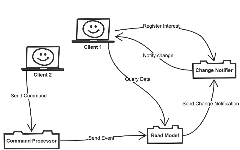
There’s a lot to learn about Event Consistency if you’re new to the topic. However, one important aspect is quickly apparent. I am often asked this question when I explain the basics of event sourcing. How does the client know when a command finished executing and what the result was? The answer is that the client doesn’t know. Or, at least it doesn’t find out directly from the Command Processor via a return channel. An example diagram (Fig. 9) shows how the problem of updating a client when changes to a Read model can be solved.
Fig. 9: Updating a client when changes are made to a Read Model
The diagram shows Client 1 sending a query to the Read Model. What’s new is that the client can now optionally contact a Change Notifier service. This service doesn’t have anything to do with events in the system. It works as a registry for the interest of clients in specific Read Models. In the diagram, if Client 2 sends a command to the system that causes changes in the Read Model, it can notify the Change Notifier. The Change Notifier knows which clients need to be notified about the change and triggers notifications, possibly with a bidirectional web technology or, in the case of native clients, an existing direct connection.
In order to implement this solution, programmers need to think about when certain notifications are necessary when creating projection logic in the Read Model. In most cases, these decisions can’t be automated. There’s no real direct link between certain commands or events and their consequences in the form of change notifications. However, it isn’t a difficult decision to make. In the architecture, additional services aren’t a problem. From the point of view of the existing communication paths, it represents just another endpoint.
Conclusion
I hope the examples were able to show that a carefully built architecture based on CQRS and event sourcing can provide a clean communication structure. Of course, there’s a lot more to say about this, and I’d be happy to discuss it further. Advanced aspects include dealing with eventual consistency in greater detail, lifecycle management of event stores, and general considerations for handling data in the event store regarding GDPR. There are many answers, but these would unfortunately exceed the scope of this article. Please feel free to contact me if I can provide any help!
References



 6 months access to session recordings.